111 Murray St.

Image courtesy of KPF
With the change in the zoning laws in recent years, New York has seen its fair share of tall and slender towers nicked named "pencil towers". 111 Murray street falls into this category, rising to a height of 800 feet at its peak. Located in the heart of Tribeca in downtown New York, a stone throws away from the famous World Trade Center Tower One, this residential tower expresses its presence by an accentuated form that tapers outward as the tower rises upward, taking advantage of the 360 degree views. The eastern facade gently peels away allowing for greater access to views north. The taught facade reinforces the elegant form while the curvature is ideal for wind shedding. The curved corners also allow for uninterrupted views of the Hudson river and lower Manhattan.
The project is design and documented parametrically using various 3d modeling applications that are all tied together by custom designed algorithms which allow for a seamless transfer of light weight data between applications. By working in a parametric environment, design, planning and fabrication rules are coded directly into the model. The workflow developed while at KPF not only allows for a holistic design and documentation experience but also displayed benefits downstream during the fabrication process as well. Having the right information embedded in the model became beneficial for various other project stake holders, increasing the incentive for collaboration and allowing detailed accurate bids for the facade.

Image courtesy of KPF
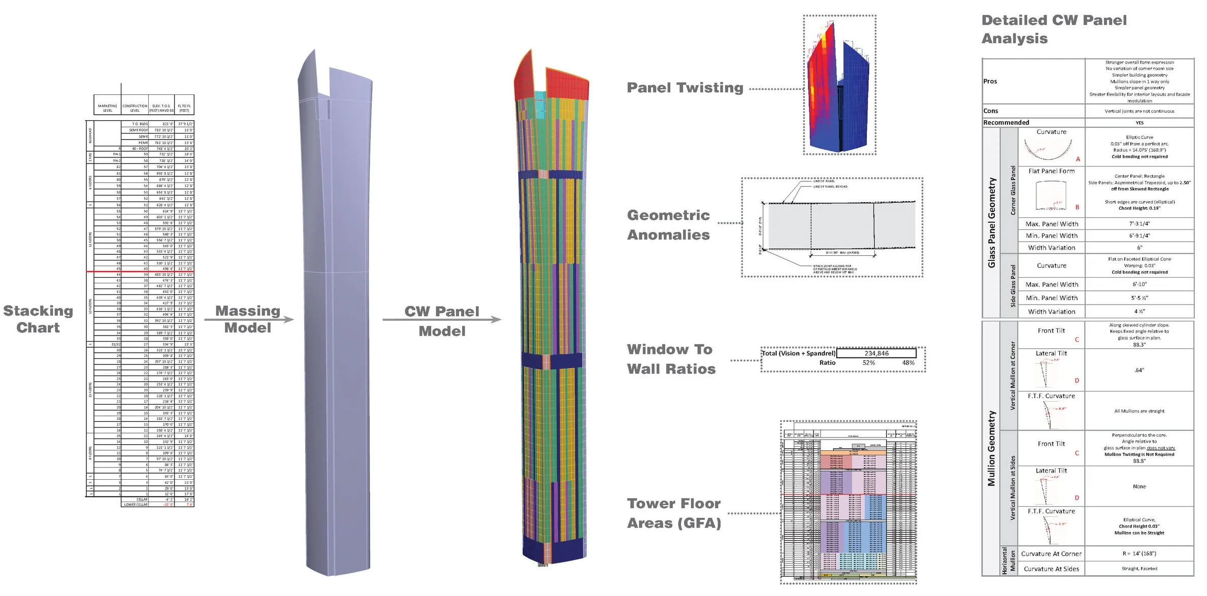
Image courtesy of KPF
The diagram above represents the aggregation of various data and rules that help drive the 3D model. The custom-built algorithms read in the planning data and are coupled with a series of geometric rules to help generate the massing. Various planning parameters such as window washing tracks, interior unit layouts, and fabrication constraints such as maximum panel twist, maximum panel dimensions, and curvature constraints are used to generate the façade wireframe model. Each of the different panel types are identified by a color-coded spreadsheet where they are easily manipulated and quantified. The seamless integration is made possible by custom plugins that were built in-house.

Image courtesy of KPF
The continuous stream of data and geometry flowing back and forth creates a working environment where models are up to date. From the image below one can identify how simple adjustments of color in a spreadsheet can have an effect downstream on the wire-frame, documentation, and visualization models.

The diagram below is a series of snapshots, identifying the critical flow of data, starting with planning and design constraints and culminating at a fabrication model. At various stages of the design process more rules are embedded in the model and a variety of analysis help transform the model from a simple geometric representation to a documentation model and later a fabrication model.

Image courtesy of KPF